Übungen GLSL und Shader
Diese Übungen dienen zum Erlernen der Grundlagen von Shadern in OpenGL. Dazu wird mithilfe einfacher Übungen die Syntax von GLSL und die Funktionsweise von GLSL-Shadern erlernt. Die Übungen bieten (absichtlich) keinen vollumfänglichen Überblick über alle Funktionen von Shadern, sondern sollen nur einen groben Einblick in die Technik gewähren.
Die Übungen können komplett auf der Website ShaderToy ausgeführt werden. Dies schränkt zwar den Funktionsumfang von OpenGL ein, hat aber den (nicht zu unterschätzenden) Vorteil, das keine Tools installiert werden müssen!
Übungen
Übung 1: Schwarz/Weiß
Aufgabe
Mithilfe der step()-Funktion kann man einen Wert mit einem Grenzwert vergleichen. Liegt der übergebene Wert über dem Grenzwert, gibt die Funktion 1 zurück, sonst 0. Zeichne mithilfe dieser Funktion die rechte Hälfte des Bildschirms in Weiß und die linke Hälfte in Schwarz.
void mainImage( out vec4 fragColor, in vec2 fragCoord )
{
  // Normalized pixel coordinates (from 0 to 1)
  vec2 uv = fragCoord/iResolution.xy;

  // pixel color
  float col = step(uv.x, 0.5);

  // Output to screen
  fragColor = vec4(col, col, col,1.0);
}
Übung 2: Rechteck zeichnen
Aufgabe
Zeichne mithilfe der step()-Funktion aus der letzten Übung ein Rechteck in der Mitte des Bildschirms. Überlege dir, woraus ein Rechteck im Kontext von GLSL bestehen könnte und implementiere die entsprechende Funktion im Shader.
Bonusaufgabe: Verschiebe das Rechteck anschließend auf verschiedene Positionen des Bildschirms.
void mainImage( out vec4 fragColor, in vec2 fragCoord )
{
   // Normalized pixel coordinates (from 0 to 1)
   vec2 uv = fragCoord/iResolution.xy;

   // pixel color
   float col1 = step(uv.x, 0.8);
   float col2 = step(uv.y, 0.8);
   float col3 = step(1.0-uv.x, 0.8);
   float col4 = step(1.0-uv.y, 0.8);

   float col = col1 * col2 * col3 * col4;

   // Output to screen
   fragColor = vec4(col, col, col,1.0);
}
Übung 3: Funktionen und if-Statements
Aufgabe
GLSL erlaubt die Erstellung von Funktionen und die Nutzung von if-Statements, um den Code besser zu struktureren. Extrahiere die Erstellung eines Rechtecks in eine separate Funktion rectangle() und rufe diese auf. Überlege dir dabei, welche Parameter die Funktion übergeben bekommen soll und was die Funktion zurückgibt.
Bonusaufgabe: Nutze if-Statements, um das Rechteck zu erstellen (anstelle der step()-Funktion).
vec3 rectangle(vec2 coord, vec2 center, float width, float height) {
    float w = width / 2.0;
    float h = height / 2.0;

    if (coord.x >= center.x - w
    && coord.x <= center.x + w
    && coord.y >= center.y - h
    && coord.y <= center.y + h) {
        return vec3(1.0, 0.0, 0.0);
    }

    return vec3(0.0, 0.0, 0.0);
}

void mainImage( out vec4 fragColor, in vec2 fragCoord )
{
    // Normalized pixel coordinates (from 0 to 1)
    vec2 uv = fragCoord.xy/iResolution.xy;

    vec3 col = rectangle(uv, vec2(0.5, 0.5), 0.2, 0.2);

    // Output to screen
    fragColor = vec4(col, 1.0);
}
float rectangle(vec2 coord, vec2 center, float width, float height) {
    float w = width / 2.0;
    float h = height / 2.0;

    if (coord.x >= center.x - w
    && coord.x <= center.x + w
    && coord.y >= center.y - h
    && coord.y <= center.y + h) {
        return 1.0;
    }

    return 0.0;
}

void mainImage( out vec4 fragColor, in vec2 fragCoord )
{
    // Normalized pixel coordinates (from 0 to 1)
    vec2 uv = fragCoord.xy/iResolution.xy;

    vec3 red = vec3(1., 0., 0.);

    vec3 col = red * rectangle(uv, vec2(0.5, 0.5), 0.2, 0.2);

    // Output to screen
    fragColor = vec4(col, 1.0);
}
Übung 4: Mouse-Position nutzen
Aufgabe
Das Tool ShaderToy bietet als uniform-Input auch die aktuelle Position der Maus. Diese wird in der Variable iMouse (Typ vec4) übergeben. Die Variable liefert dabei die folgenden Werte:
mouse.xy = Mouse-Position beim letzten Mouse-Button Down
abs(mouse.zw) = Mouse-Position beim letzten Mouse-Button Click
sign(mouze.z) = Mouse-Button ist gedrückt (positiv, wenn gedrückt)
sign(mouze.w) = Mouse-Button ist geklickt (positiv, wenn geklickt)
Nutze die Mouse-Position, um das Rechteck immer dort zu zeichnen, wo die Mouse hinklickt.
vec3 rectangle(vec2 coord, vec2 center, float width, float height) {
    float w = width / 2.0;
    float h = height / 2.0;

    if (coord.x >= center.x - w
    && coord.x <= center.x + w
    && coord.y >= center.y - h
    && coord.y <= center.y + h) {
        return vec3(1.0, 0.0, 0.0);
    }

    return vec3(0.0, 0.0, 0.0);
}

void mainImage( out vec4 fragColor, in vec2 fragCoord )
{
    // Normalized pixel coordinates (from 0 to 1)
    vec2 uv = fragCoord.xy/iResolution.xy;

    vec2 mv = iMouse.xy/iResolution.xy;

    vec3 col = rectangle(uv, mv, 0.2, 0.2);

    // Output to screen
    fragColor = vec4(col, 1.0);
}
Übung 5: Animation
Aufgabe
Animationen sind ein Grundpfeiler der interaktiven Computergrafik. Damit ein Shader in GLSL animiert werden kann, muss über eine Variable der "Takt" der Animation vorgegeben werden. Dazu gibt es in ShaderToy die Variable iTime, die die abgelaufene Zeit seit dem Start des Shaders anzeigt. Die Zeit lässt sich im Anzeigefenster pausieren und anzeigen (gut zum debuggen).
Lass das rote Rechteck aus Übung 4 pulsieren (wie ein Herz). Ändere auch die Geschwindigkeit des Pulses und das Ausmaß der Größenänderung.
Bonusaufgabe: Erstelle Animationen mit den verschiedenen Funktionen sin(), cos(), tan()und mod(). Was ist jeweils der Unterschied und die Auswirkung auf die Animation?
vec3 rectangle(vec2 coord, vec2 center, float width, float height) {
    float w = width / 2.0;
    float h = height / 2.0;

    if (coord.x >= center.x - w
    && coord.x <= center.x + w
    && coord.y >= center.y - h
    && coord.y <= center.y + h) {
        return vec3(1.0, 0.0, 0.0);
    }

    return vec3(0.0, 0.0, 0.0);
}

void mainImage( out vec4 fragColor, in vec2 fragCoord )
{
    // Normalized pixel coordinates (from 0 to 1)
    vec2 uv = fragCoord.xy/iResolution.xy;

    vec2 mv = iMouse.xy/iResolution.xy;

    float pulse = sin(iTime*5.0)*0.1;

    vec3 col = rectangle(uv, mv, pulse + 0.2, pulse + 0.2);

    // Output to screen
    fragColor = vec4(col, 1.0);
}
Übung 6: Mehrere Objekte
Aufgabe
Bisher haben wir nur ein Rechteck gezeichnet. Meist benötigt man in der Computergrafik aber mehrere Objekte in einer Szene. Dabei gibt es zusätzliche Hindernisse, die man beachten muss (z. B. welches Objekt liegt vor welchem anderen).
Füge zusätzlich zum Maus-gesteuerten Objekt aus Übung 5 mehrere weitere Rechtecke in einer anderen Farbe (z. B. gelb) ein. Wie kann beeinflusst werden, welches Objekt vor welchen anderen liegt? Probiert verschiedene Ansätze aus.
Contents
float rectangle(vec2 coord, vec2 center, float width, float height) {
    float w = width / 2.0;
    float h = height / 2.0;

    if (coord.x >= center.x - w
    && coord.x <= center.x + w
    && coord.y >= center.y - h
    && coord.y <= center.y + h) {
        return 1.0;
    }

    return 0.0;
}

void mainImage( out vec4 fragColor, in vec2 fragCoord )
{
    // Normalized pixel coordinates (from 0 to 1)
    vec2 uv = fragCoord.xy/iResolution.xy;

    vec2 mv = iMouse.xy/iResolution.xy;

    float pulse = sin(iTime*5.0)*0.1;

    vec3 finalColor;

    finalColor += vec3(1.0, 1.0, 0.0) * rectangle(uv, vec2(0.25, 0.25), 0.2, 0.2);
    finalColor += vec3(1.0, 1.0, 0.0) * rectangle(uv, vec2(0.25, 0.75), 0.2, 0.2);
    finalColor += vec3(1.0, 1.0, 0.0) * rectangle(uv, vec2(0.75, 0.75), 0.2, 0.2);
    finalColor += vec3(1.0, 1.0, 0.0) * rectangle(uv, vec2(0.75, 0.25), 0.2, 0.2);
    finalColor += vec3(1.0, 0.0, 0.0) * rectangle(uv, mv, pulse + 0.2, pulse + 0.2);

    // Output to screen
    fragColor = vec4(finalColor, 1.0);
}
Übung 7: Kreise und Distancefields
Oft werden Objekte in OpenGL nicht direkt über ihre mathematische Definition gezeichnet, sondern werden anhand eines Distancefields berechnet.
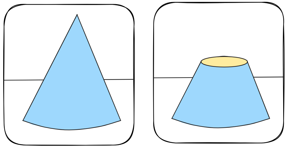
Am Beispiel des Kreises wird schnell klar, wie Distancefields funktionieren:
Stell dir vor, du stehst oben auf der Spitze eines Kegels. Der horizontale Abstand zum Rand des Kegels ist 0,5 in alle Richtungen. Wenn du dich nun entscheidest, bei welcher Distanz du den Kegel "abschneiden" willst, erhältst du mehr oder weniger große Kreise.
Aufgabe
Wende ein Distancefield an, um statt der Rechtecke aus Übung 5 Kreise in deiner Szene zu zeichnen.
Überlege dir dabei, wie du das relative Koordinatensystem an das Seitenverhältnis des Bildschirms anpassen kannst, damit deine Kreise rund und nicht elliptisch sind.
Bonusaufgabe: Animiere die Farben der Kreise und die Bewegung der Kreise.
// signed distance field circle
float sdfCircle(vec2 uv, float r, vec2 offset) {
  float x = uv.x - offset.x;
  float y = uv.y - offset.y;

  float d = length(vec2(x, y)) - r;

  return d > 0. ? 0. : 1.;
}

void mainImage( out vec4 fragColor, in vec2 fragCoord )
{
    // Normalized pixel coordinates (from 0 to 1)
    vec2 uv = fragCoord.xy/iResolution.xy;

    // Koordinatensystem in die Mitte verschieben
    uv -= 0.5;

    // Anpassung An Aspect ratio
    uv.x *= iResolution.x/iResolution.y; // fix aspect ratio

    vec2 mv = iMouse.xy/iResolution.xy;

    vec3 baseColor = 0.5 + 0.5 * cos(iTime + uv.xyx + vec3(0,2,4));

    vec3 finalColor;

    finalColor += baseColor * sdfCircle(uv, .2, vec2(.25, .25));
    finalColor += baseColor * sdfCircle(uv, .2, vec2(.25, -.25));
    finalColor += baseColor * sdfCircle(uv, .2, vec2(-.25, .25));
    finalColor += baseColor * sdfCircle(uv, .2, vec2(-.25, -.25));

    // Output to screen
    fragColor = vec4(finalColor, 1.0);
}
Übung 8: Radar-Anzeige
Wir haben nun verschiedene Werkzeuge kennengelernt, um zweidimensionale Bilder in GLSL-Shadern zu erzeugen. Füge dein Wissen nun zusammen und baue eine komplexere Szene in GLSL nach.
In GLSL gibt es die Möglichkeit Preprocessor Directives zu nutzen, um Konstanten zu definieren. Das Schlüsselwort dafür ist #define. Die Werte könnten genauso wie normale const-Konstanten in deinem GLSL-Code genutzt werden.
Aufgabe
Erstelle eine komplexe(re) 2D-Szene mit mehreren Objekten, Animation und Mouse-Position.
Vorbild für die Szene soll die (animierte und interaktive) Ansicht eines Radars sein.
So soll deine Animation am Ende aussehen:
#define M_PI 3.1415926535897932384626433832795

// signed distance field circle
float sdfCircleOutline(vec2 uv, float r, vec2 offset, float width) {
  float x = uv.x - offset.x;
  float y = uv.y - offset.y;

  float d = length(vec2(x, y)) - r;

  // smooth circle:
  return smoothstep(0., width, d) - smoothstep(width, width+0.002, d);

  // alternative: non-smooth circle:
  return (d > 0. && d < width) ? 1. : 0.;
}

float sdfCircleFilled(vec2 uv, float r, vec2 offset) {
  float x = uv.x - offset.x;
  float y = uv.y - offset.y;

  float d = length(vec2(x, y)) - r;

  return d < 0. ? 1. : 0.;
}

float animatedLine(vec2 uv, vec2 center, float radius, float width) {
    float angle = 90. * iTime;
    float r = distance(uv, center);

    // cap line out of radius
    if(r>radius) return 0.;

    //compute the distance to the line
    vec2 d = uv - center;

    // rotation matrix
    vec2 p = radius*vec2(cos(angle*M_PI/180.),
                        -sin(angle*M_PI/180.));
    float l = length( d - p*clamp( dot(d,p)/dot(p,p), 0., 1.) );
    return 1.0 - smoothstep(0.0, width, l);
}

void mainImage( out vec4 fragColor, in vec2 fragCoord )
{
    vec2 uv = fragCoord.xy/iResolution.xy; // normalize (from 0 to 1)
    uv -= 0.5; // move to center
    uv.x *= iResolution.x/iResolution.y; // fix aspect ratio

    vec2 mv = iMouse.xy/iResolution.xy;
    mv -= 0.5;
    mv.x *= iResolution.x/iResolution.y;

    vec3 finalColor;

    // white circles
    finalColor += vec3(1., 1., 1.) * sdfCircleOutline(uv, .1, vec2(.0, .0), 0.005);
    finalColor += vec3(1., 1., 1.) * sdfCircleOutline(uv, .25, vec2(.0, .0), 0.005);
    finalColor += vec3(1., 1., 1.) * sdfCircleOutline(uv, .4, vec2(.0, .0), 0.005);

    // blue moving line
    finalColor += vec3(0.35,0.76,0.83) * animatedLine(uv, vec2(.0, .0), 0.4, 0.005);

    // red circle
    finalColor += vec3(1.0, 0.0, 0.0) * sdfCircleFilled(uv, .01, mv);
    finalColor += vec3(1.0, 0.0, 0.0) * sdfCircleOutline(uv, mod(iTime*.15, 0.15), mv, 0.005);

    // Output to screen
    fragColor = vec4(finalColor, 1.0);
}
Übung 9: Raymarching (3D-Objekte)
2D-Objekte haben wir jetzt schon reichlich gesehen, aber was ist mit 3D-Objekten? Unsere Szene nutzt für 3D-Objekte die "Rechte-Hand-Regel". Um dann 3D-Objekte zu zeichnen brauchen wir einen Algorithmus der die Beleuchtung simuliert. Dafür bietet sich entweder der Raytracing oder der Raymarching-Algorithmus an.
Aufgabe
Schau dir die Implementierung des Raymarching-Algorithmus in der Lösung unten an (oder implementiere ihn selbst) und zeichne anschließend eine beleuchtete Kugel in der Mitte des Bildschirms. Teste verschiedene Parameter für die Farbe der Kugel und die Beleuchtung.
Eine sehr gute Step-by-Step Erklärung des Algorithmus findest du hier: Link
const int MAX_MARCHING_STEPS = 255;
const float MIN_DIST = 0.0;
const float MAX_DIST = 100.0;
const float PRECISION = 0.001;

float sdSphere(vec3 p, float r )
{
  vec3 offset = vec3(0, 0, -2);
  return length(p - offset) - r;
}

float rayMarch(vec3 ro, vec3 rd, float start, float end) {
  float depth = start;

  for (int i = 0; i < MAX_MARCHING_STEPS; i++) {
    vec3 p = ro + depth * rd;
    float d = sdSphere(p, 1.);
    depth += d;
    if (d < PRECISION || depth > end) break;
  }

  return depth;
}

vec3 calcNormal(vec3 p) {
    vec2 e = vec2(1.0, -1.0) * 0.0005; // epsilon
    float r = 1.; // radius of sphere
    return normalize(
      e.xyy * sdSphere(p + e.xyy, r) +
      e.yyx * sdSphere(p + e.yyx, r) +
      e.yxy * sdSphere(p + e.yxy, r) +
      e.xxx * sdSphere(p + e.xxx, r));
}

void mainImage( out vec4 fragColor, in vec2 fragCoord )
{
  vec2 uv = (fragCoord-.5*iResolution.xy)/iResolution.y;

  vec3 col = vec3(0);
  vec3 ro = vec3(0, 0, 3); // ray origin that represents camera position
  vec3 rd = normalize(vec3(uv, -1)); // ray direction

  float d = rayMarch(ro, rd, MIN_DIST, MAX_DIST); // distance to sphere

  if (d > MAX_DIST) {
    col = vec3(0.6); // ray didn't hit anything
  } else {
    vec3 p = ro + rd * d; // point on sphere we discovered from ray marching
    vec3 normal = calcNormal(p);
    vec3 lightPosition = vec3(2, 2, 4);
    vec3 lightDirection = normalize(lightPosition - p);

    // Calculate diffuse reflection by taking the dot product of
    // the normal and the light direction.
    float dif = clamp(dot(normal, lightDirection), 0., 1.);

    col = vec3(dif);
  }

  // Output to screen
  fragColor = vec4(col, 1.0);
}
Übung 10: Mehrere 3D-Objekte
Nun möchten wir natürlich nicht nur eine Kugel darstellen, sondern auch mehrere 3D-Objekte dargestellt können. Dazu benötigen wir eine Funktion sdScene(), die berechnet, welches Objekt gerade vorne liegt und die die verschiedenen 3D-Objekte miteinander verknüpft. Die sdScene()-Methode wird dann an allen Stellen statt der sdSphere()-Methode genutzt.
Aufgabe
Implementiere die scScene()-Methode und baue deinen Code aus Übung 9 entsprechend um.
Bonusaufgabe: Nutze den Link unten zu den Distance Functions und füge verschiedene Objekte in deine Szene ein.
const int MAX_MARCHING_STEPS = 255;
const float MIN_DIST = 0.0;
const float MAX_DIST = 100.0;
const float PRECISION = 0.001;

float sdSphere(vec3 p, float r, vec3 offset )
{
  return length(p - offset) - r;
}

float sdCappedTorus( vec3 p, vec2 sc, float ra, float rb, vec3 offset)
{
  p = p - offset;

  p.x = abs(p.x);
  float k = (sc.y*p.x>sc.x*p.y) ? dot(p.xy,sc) : length(p.xy);
  return sqrt( dot(p,p) + ra*ra - 2.0*ra*k ) - rb;
}

float sdScene(vec3 p) {
  float sphere = sdSphere(p, 1., vec3(-2, 0, -2));
  float torus = sdCappedTorus(p, vec2(0.0, 0.0), 0.4, .1, vec3(1, 0, 0));
  return min(sphere, torus);
}

float rayMarch(vec3 ro, vec3 rd, float start, float end) {
  float depth = start;

  for (int i = 0; i < MAX_MARCHING_STEPS; i++) {
    vec3 p = ro + depth * rd;
    float d = sdScene(p);
    depth += d;
    if (d < PRECISION || depth > end) break;
  }

  return depth;
}

vec3 calcNormal(in vec3 p) {
    vec2 e = vec2(1.0, -1.0) * 0.0005; // epsilon
    float r = 1.; // radius of sphere
    return normalize(
      e.xyy * sdScene(p + e.xyy) +
      e.yyx * sdScene(p + e.yyx) +
      e.yxy * sdScene(p + e.yxy) +
      e.xxx * sdScene(p + e.xxx));
}

void mainImage( out vec4 fragColor, in vec2 fragCoord )
{
  vec2 uv = (fragCoord-.5*iResolution.xy)/iResolution.y;
  vec3 backgroundColor = vec3(0.835, 1, 1);

  vec3 col = vec3(0);
  vec3 ro = vec3(0, 0, 3); // ray origin that represents camera position
  vec3 rd = normalize(vec3(uv, -1)); // ray direction

  float d = rayMarch(ro, rd, MIN_DIST, MAX_DIST); // distance to sphere

  if (d > MAX_DIST) {
    col = backgroundColor; // ray didn't hit anything
  } else {
    vec3 p = ro + rd * d; // point on sphere we discovered from ray marching
    vec3 normal = calcNormal(p);
    vec3 lightPosition = vec3(2, 2, 7);
    vec3 lightDirection = normalize(lightPosition - p);

    // Calculate diffuse reflection by taking the dot product of
    // the normal and the light direction.
    float dif = clamp(dot(normal, lightDirection), 0.3, 1.);

    // Multiply the diffuse reflection value by an orange color and add a bit
    // of the background color to the sphere to blend it more with the background.
    col = dif * vec3(1, 0.58, 0.29) + backgroundColor * .2;
  }

  // Output to screen
  fragColor = vec4(col, 1.0);
}
Übung 11: Individuelle Farben
Bisher hat jedes unserer 3D-Objekte die selbe Farbe genutzt. Wir können die Farbe gesammelt für alle Objekte in unserer Szene anpassen, können den Objekten aber keine unterschiedlichen Farben zuweisen. Um dies zu ermöglichen, müssen wir die Distancefield-Funktionen anpassen, sodass sie nicht nur die Distanz sondern auch die gewünschte Farbe des Objekts zurückgeben.
Es gibt verschiedene Wege das umzusetzen (z. B. vec4), wir nutzen aber structs als Möglichkeit den Code sauber zu ordnen und übersichtlicher zu gestalten. Structsgibt es auch in Programmiersprachen wie C++ und sind ähnlich zu "Klassen" in anderen Programmiersprachen.
Aufgabe
Bau deinen Code aus Übung 10 so um, dass mehrere Farben für die Objekte genutzt werden können. Nutze dafür structs. Überlege dir welche Stellen deines Codes angepasst werden müssen, um die Farbwerte weiterzugeben und auszuwerten.
Bonusaufgabe: Füge einen Fußboden bzw. Untergrund unter den 3D-Objekten hinzu.
const int MAX_MARCHING_STEPS = 255;
const float MIN_DIST = 0.0;
const float MAX_DIST = 100.0;
const float PRECISION = 0.001;

struct Surface {
  float dist;
  vec3 color;
};

Surface sdSphere(vec3 p, float r, vec3 offset, vec3 col )
{
  return Surface(length(p - offset) - r, col);
}

Surface sdCappedTorus( vec3 p, vec2 sc, float ra, float rb, vec3 offset, vec3 col)
{
  p = p - offset;

  p.x = abs(p.x);
  float k = (sc.y*p.x>sc.x*p.y) ? dot(p.xy,sc) : length(p.xy);
  return Surface(sqrt( dot(p,p) + ra*ra - 2.0*ra*k ) - rb, col);
}

Surface sdFloor(vec3 p, vec3 col) {
  float d = p.y + 1.;
  return Surface(d, col);
}

Surface minWithSurface( Surface s1, Surface s2 ) {
  if (s2.dist < s1.dist) return s2;
  return s1;
}

Surface sdScene(vec3 p) {
  Surface sphere = sdSphere(p, 1., vec3(-2, 0, -2), vec3(1., 0., 0.));
  Surface torus = sdCappedTorus(p, vec2(0.0, 0.0), 0.4, .1, vec3(1, 0, 0), vec3(1., .5, .5));
  Surface bottomFloor = sdFloor(p, vec3(1. + 0.7*mod(floor(p.x) + floor(p.z), 2.0)));
  return minWithSurface(bottomFloor, minWithSurface(sphere, torus));
}

Surface rayMarch(vec3 ro, vec3 rd, float start, float end) {
  float depth = start;
  Surface closestObject; // closest object

  for (int i = 0; i < MAX_MARCHING_STEPS; i++) {
    vec3 p = ro + depth * rd;
    closestObject = sdScene(p);
    depth += closestObject.dist;
    if (closestObject.dist < PRECISION || depth > end) break;
  }

  closestObject.dist = depth;

  return closestObject;
}

vec3 calcNormal(in vec3 p) {
    vec2 e = vec2(1.0, -1.0) * 0.0005; // epsilon
    float r = 1.; // radius of sphere
    return normalize(
      e.xyy * sdScene(p + e.xyy).dist +
      e.yyx * sdScene(p + e.yyx).dist +
      e.yxy * sdScene(p + e.yxy).dist +
      e.xxx * sdScene(p + e.xxx).dist);
}

void mainImage( out vec4 fragColor, in vec2 fragCoord )
{
  vec2 uv = (fragCoord-.5*iResolution.xy)/iResolution.y;
  vec3 backgroundColor = vec3(0.835, 1, 1);

  vec3 col = vec3(0);
  vec3 ro = vec3(0, 0, 3); // ray origin that represents camera position
  vec3 rd = normalize(vec3(uv, -1)); // ray direction

  Surface clostObject = rayMarch(ro, rd, MIN_DIST, MAX_DIST); // distance to sphere

  if (clostObject.dist > MAX_DIST) {
    col = backgroundColor; // ray didn't hit anything
  } else {
    vec3 p = ro + rd * clostObject.dist; // point on sphere we discovered from ray marching
    vec3 normal = calcNormal(p);
    vec3 lightPosition = vec3(2, 2, 7);
    vec3 lightDirection = normalize(lightPosition - p);

    float dif = clamp(dot(normal, lightDirection), 0.3, 1.);

    col = dif * clostObject.color + backgroundColor * .2;
  }

  // Output to screen
  fragColor = vec4(col, 1.0);
}
Übung 12: Rotation
Als nächstes schauen wir uns die Rotation von Objekten in unserer Szene an. Damit können wir z. B. Rechtecke oder den Ring aus den vorherigen Übungen von der Seite ansehen. Um die Auswirkungen der Rotation besser sehen zu können tauschen wir zunächst die Kugel gegen ein Rechteck mit der Funktion sdBox. Wie das geht, solltest du aus den vorherigen Übungen bereits wissen.
Rotationen bauen auf Rotationsmatrizen auf. Um diese Matrizen in GLSL darzustellen gibt es die Datentypen mat*. In unserem Fall kann die Rotationsmatrix dann über den Datentypen mat3dargestellt werden.
Aufgabe
Implementiere eine Funktion für die Rotation in x-, y- und z-Richtung und passe deine Objekt-Funktionen entsprechend an, um eine Rotationsmatrix entgegenzunehmen.
Bonusaufgabe: Wie können nun Objekte gezeichnet werden, die keinerlei Rotation/Transformation unterliegen. Implementiere eine entsprechende mat3-Konstante, die in diesem Fall genutzt werden kann.
Bonusaufgabe: Animiere die Rotation über die Variable iTime.
const int MAX_MARCHING_STEPS = 255;
const float MIN_DIST = 0.0;
const float MAX_DIST = 100.0;
const float PRECISION = 0.001;
mat3 IDENTITY = mat3(
        vec3(1, 0, 0),
        vec3(0, 1, 0),
        vec3(0, 0, 1)
    );

// Rotation matrix around the X axis.
mat3 rotateX(float theta) {
    float c = cos(theta);
    float s = sin(theta);
    return mat3(
        vec3(1, 0, 0),
        vec3(0, c, -s),
        vec3(0, s, c)
    );
}

// Rotation matrix around the Y axis.
mat3 rotateY(float theta) {
    float c = cos(theta);
    float s = sin(theta);
    return mat3(
        vec3(c, 0, s),
        vec3(0, 1, 0),
        vec3(-s, 0, c)
    );
}

// Rotation matrix around the Z axis.
mat3 rotateZ(float theta) {
    float c = cos(theta);
    float s = sin(theta);
    return mat3(
        vec3(c, -s, 0),
        vec3(s, c, 0),
        vec3(0, 0, 1)
    );
}

struct Surface {
  float dist;
  vec3 color;
};

vec3 transform(vec3 p, vec3 moveOffset, mat3 rotation) {
    return (p - moveOffset)*rotation;
}

Surface sdBox( vec3 p, vec3 b, vec3 col)
{
  vec3 q = abs(p) - b;
  return Surface(length(max(q,0.0)) + min(max(q.x,max(q.y,q.z)),0.0), col);
}

Surface sdCappedTorus( vec3 p, vec2 sc, float ra, float rb, vec3 col)
{
  p.x = abs(p.x);
  float k = (sc.y*p.x>sc.x*p.y) ? dot(p.xy,sc) : length(p.xy);
  return Surface(sqrt( dot(p,p) + ra*ra - 2.0*ra*k ) - rb, col);
}

Surface sdFloor(vec3 p, vec3 col) {
  float d = p.y + 1.;
  return Surface(d, col);
}

Surface minWithSurface( Surface s1, Surface s2 ) {
  if (s2.dist < s1.dist) return s2;
  return s1;
}

Surface sdScene(vec3 p) {
  Surface box = sdBox(transform(p, vec3(-1.5, 0, -1.5), rotateX(iTime)), vec3(.4, .4, .4), vec3(1., 0., 0.));
  Surface torus = sdCappedTorus(transform(p,  vec3(1, 0, 0), rotateY(iTime)), vec2(0.0, 0.0), 0.4, .1, vec3(1., .5, .5));
  Surface bottomFloor = sdFloor(p, vec3(1. + 0.7*mod(floor(p.x) + floor(p.z), 2.0)));
  return minWithSurface(bottomFloor, minWithSurface(box, torus));
}

Surface rayMarch(vec3 ro, vec3 rd, float start, float end) {
  float depth = start;
  Surface closestObject; // closest object

  for (int i = 0; i < MAX_MARCHING_STEPS; i++) {
    vec3 p = ro + depth * rd;
    closestObject = sdScene(p);
    depth += closestObject.dist;
    if (closestObject.dist < PRECISION || depth > end) break;
  }

  closestObject.dist = depth;

  return closestObject;
}

vec3 calcNormal(in vec3 p) {
    vec2 e = vec2(1.0, -1.0) * 0.0005; // epsilon
    float r = 1.; // radius of sphere
    return normalize(
      e.xyy * sdScene(p + e.xyy).dist +
      e.yyx * sdScene(p + e.yyx).dist +
      e.yxy * sdScene(p + e.yxy).dist +
      e.xxx * sdScene(p + e.xxx).dist);
}

void mainImage( out vec4 fragColor, in vec2 fragCoord )
{
  vec2 uv = (fragCoord-.5*iResolution.xy)/iResolution.y;
  vec3 backgroundColor = vec3(0.835, 1, 1);

  vec3 col = vec3(0);
  vec3 ro = vec3(0, 0, 3); // ray origin that represents camera position
  vec3 rd = normalize(vec3(uv, -1)); // ray direction

  Surface clostObject = rayMarch(ro, rd, MIN_DIST, MAX_DIST); // distance to sphere

  if (clostObject.dist > MAX_DIST) {
    col = backgroundColor; // ray didn't hit anything
  } else {
    vec3 p = ro + rd * clostObject.dist; // point on sphere we discovered from ray marching
    vec3 normal = calcNormal(p);
    vec3 lightPosition = vec3(2, 2, 7);
    vec3 lightDirection = normalize(lightPosition - p);

    float dif = clamp(dot(normal, lightDirection), 0.3, 1.);

    col = dif * clostObject.color + backgroundColor * .2;
  }

  // Output to screen
  fragColor = vec4(col, 1.0);
}
Übung 13: Constructive Solid Geometry (CSG)
In der Vorlesung haben wir schon die Constructive Solid Geometry (CSG) kennengelernt, deren Grundgedanke es ist, komplexe Formen als eine Kombination aus simplen Grundformen darzustellen (Kugel, Rechteck, Zylinder, ...). Grundzüge der CSG kann man auch in GLSL nachbauen. Dafür ist eine Änderung der Methode sdScene()notwendig.
Aufgabe
Baue die Methode sdScene() so um, dass ein komplexes Objekt aus verschiedenen Grundformen entsteht. Dies kann zum Beispiel ein Rechteck mit einem kreisförmigen Loch sein oder ein anderes Objekt deiner Wahl. Beispiel-Implementierungen für die Mengenoperationen findet ihr unter dem Link unten zu den Distancefunctions.
const int MAX_MARCHING_STEPS = 255;
const float MIN_DIST = 0.0;
const float MAX_DIST = 100.0;
const float PRECISION = 0.001;
mat3 IDENTITY = mat3(
        vec3(1, 0, 0),
        vec3(0, 1, 0),
        vec3(0, 0, 1)
    );

// Rotation matrix around the X axis.
mat3 rotateX(float theta) {
    float c = cos(theta);
    float s = sin(theta);
    return mat3(
        vec3(1, 0, 0),
        vec3(0, c, -s),
        vec3(0, s, c)
    );
}

// Rotation matrix around the Y axis.
mat3 rotateY(float theta) {
    float c = cos(theta);
    float s = sin(theta);
    return mat3(
        vec3(c, 0, s),
        vec3(0, 1, 0),
        vec3(-s, 0, c)
    );
}

// Rotation matrix around the Z axis.
mat3 rotateZ(float theta) {
    float c = cos(theta);
    float s = sin(theta);
    return mat3(
        vec3(c, -s, 0),
        vec3(s, c, 0),
        vec3(0, 0, 1)
    );
}

struct Surface {
  float dist;
  vec3 color;
};

vec3 transform(vec3 p, vec3 moveOffset, mat3 rotation) {
    return (p - moveOffset)*rotation;
}

Surface sdBox( vec3 p, vec3 b, vec3 col)
{
  vec3 q = abs(p) - b;
  return Surface(length(max(q,0.0)) + min(max(q.x,max(q.y,q.z)),0.0), col);
}

Surface sdCappedCylinder( vec3 p, float h, float r, vec3 col )
{
  vec2 d = abs(vec2(length(p.xz),p.y)) - vec2(r,h);
  return Surface(min(max(d.x,d.y),0.0) + length(max(d,0.0)), col);
}

Surface sdFloor(vec3 p, vec3 col) {
  float d = p.y + 1.;
  return Surface(d, col);
}

Surface opUnion( Surface s1, Surface s2 ) {
  if (s2.dist < s1.dist) return s2;
  return s1;
}

Surface opSubtract( Surface s1, Surface s2 ) {
  if (-s1.dist > s2.dist) {
      s1.dist = -s1.dist;
      return s1;
  }
  return s2;
}

Surface sdScene(vec3 p) {
  Surface box = sdBox(transform(p, vec3(0, 0, 0), rotateY(10.)), vec3(.4, .4, .8), vec3(1., 0., 0.));
  Surface cylinder = sdCappedCylinder(transform(p, vec3(0, 0, 0), rotateZ(50.)*rotateX(30.)), 1., .2, vec3(0, 0, 1.));
  Surface bottomFloor = sdFloor(p, vec3(1. + 0.7*mod(floor(p.x) + floor(p.z), 2.0)));
  return opUnion(bottomFloor, opSubtract(cylinder, box));
}

Surface rayMarch(vec3 ro, vec3 rd, float start, float end) {
  float depth = start;
  Surface closestObject;

  for (int i = 0; i < MAX_MARCHING_STEPS; i++) {
    vec3 p = ro + depth * rd;
    closestObject = sdScene(p);
    depth += closestObject.dist;
    if (closestObject.dist < PRECISION || depth > end) break;
  }

  closestObject.dist = depth;

  return closestObject;
}

vec3 calcNormal(in vec3 p) {
    vec2 e = vec2(1.0, -1.0) * 0.0005; // epsilon
    float r = 1.; // radius of sphere
    return normalize(
      e.xyy * sdScene(p + e.xyy).dist +
      e.yyx * sdScene(p + e.yyx).dist +
      e.yxy * sdScene(p + e.yxy).dist +
      e.xxx * sdScene(p + e.xxx).dist);
}

void mainImage( out vec4 fragColor, in vec2 fragCoord )
{
  vec2 uv = (fragCoord-.5*iResolution.xy)/iResolution.y;
  vec3 backgroundColor = vec3(0.835, 1, 1);

  vec3 col = vec3(0);
  vec3 ro = vec3(0, 0, 3); // ray origin that represents camera position
  vec3 rd = normalize(vec3(uv, -1)); // ray direction

  Surface clostObject = rayMarch(ro, rd, MIN_DIST, MAX_DIST); // distance to sphere

  if (clostObject.dist > MAX_DIST) {
    col = backgroundColor; // ray didn't hit anything
  } else {
    vec3 p = ro + rd * clostObject.dist; // point on sphere we discovered from ray marching
    vec3 normal = calcNormal(p);
    vec3 lightPosition = vec3(2, 2, 7);
    vec3 lightDirection = normalize(lightPosition - p);

    float dif = clamp(dot(normal, lightDirection), 0.3, 1.);

    col = dif * clostObject.color + backgroundColor * .2;
  }

  // Output to screen
  fragColor = vec4(col, 1.0);
}
Übung 14: Kamerabewegung
Nicht in jeder 3D-Szene ist es ausreichend die Objekte zu zeichnen und zu transformieren. Manchmal ist es auch notwendig, die Kameraperspektive an sich zu ändern, um mit der Szene zu interagieren.
Aufgabe
Implementiere die Kamerabewegung, indem du die Variable ro(ray origin) anpasst. Dazu kannst du die bekannten Transformationen für 3D-Objekte nutzen (Rotation/Bewegung).
Bonusaufgabe: Implementiere die Kamerabewegung abhängig von der aktuellen Maus-Position, damit man die Kameraperspektive über Mouse-Drag-Gesten anpassen kann.
const int MAX_MARCHING_STEPS = 255;
const float MIN_DIST = 0.0;
const float MAX_DIST = 100.0;
const float PRECISION = 0.001;
mat3 IDENTITY = mat3(
        vec3(1, 0, 0),
        vec3(0, 1, 0),
        vec3(0, 0, 1)
    );

// Rotation matrix around the X axis.
mat3 rotateX(float theta) {
    float c = cos(theta);
    float s = sin(theta);
    return mat3(
        vec3(1, 0, 0),
        vec3(0, c, -s),
        vec3(0, s, c)
    );
}

// Rotation matrix around the Y axis.
mat3 rotateY(float theta) {
    float c = cos(theta);
    float s = sin(theta);
    return mat3(
        vec3(c, 0, s),
        vec3(0, 1, 0),
        vec3(-s, 0, c)
    );
}

// Rotation matrix around the Z axis.
mat3 rotateZ(float theta) {
    float c = cos(theta);
    float s = sin(theta);
    return mat3(
        vec3(c, -s, 0),
        vec3(s, c, 0),
        vec3(0, 0, 1)
    );
}

struct Surface {
  float dist;
  vec3 color;
};

vec3 transform(vec3 p, vec3 moveOffset, mat3 rotation) {
    return (p - moveOffset)*rotation;
}

Surface sdBox( vec3 p, vec3 b, vec3 col)
{
  vec3 q = abs(p) - b;
  return Surface(length(max(q,0.0)) + min(max(q.x,max(q.y,q.z)),0.0), col);
}

Surface sdFloor(vec3 p, vec3 col) {
  float d = p.y + 1.;
  return Surface(d, col);
}

Surface opUnion( Surface s1, Surface s2 ) {
  if (s2.dist < s1.dist) return s2;
  return s1;
}

Surface sdScene(vec3 p) {
  Surface box = sdBox(transform(p, vec3(0, 0, 0), rotateY(10.)), vec3(.4, .4, .8), vec3(1., 0., 0.));
  Surface bottomFloor = sdFloor(p, vec3(1. + 0.7*mod(floor(p.x) + floor(p.z), 2.0)));
  return opUnion(bottomFloor, box);
}

Surface rayMarch(vec3 ro, vec3 rd, float start, float end) {
  float depth = start;
  Surface closestObject;

  for (int i = 0; i < MAX_MARCHING_STEPS; i++) {
    vec3 p = ro + depth * rd;
    closestObject = sdScene(p);
    depth += closestObject.dist;
    if (closestObject.dist < PRECISION || depth > end) break;
  }

  closestObject.dist = depth;

  return closestObject;
}

vec3 calcNormal(in vec3 p) {
    vec2 e = vec2(1.0, -1.0) * 0.0005; // epsilon
    float r = 1.; // radius of sphere
    return normalize(
      e.xyy * sdScene(p + e.xyy).dist +
      e.yyx * sdScene(p + e.yyx).dist +
      e.yxy * sdScene(p + e.yxy).dist +
      e.xxx * sdScene(p + e.xxx).dist);
}

void mainImage( out vec4 fragColor, in vec2 fragCoord )
{
  vec2 uv = (fragCoord-.5*iResolution.xy)/iResolution.y;
  vec3 backgroundColor = vec3(0.835, 1, 1);

  vec2 mouse = iMouse.xy / iResolution.xy - 0.5; // Mouse pos between -0.5 and 0.5

  vec3 col = vec3(0);
  vec3 ro = vec3(0, 0, 3); // camera position -> move camera
  vec3 rd = normalize(vec3(uv, -1)); // ray direction
  rd = transform(rd, vec3(0,0,0), rotateY(mouse.x) * rotateX(-mouse.y)); // -> rotate camera

  Surface clostObject = rayMarch(ro, rd, MIN_DIST, MAX_DIST); // distance to sphere

  if (clostObject.dist > MAX_DIST) {
    col = backgroundColor; // ray didn't hit anything
  } else {
    vec3 p = ro + rd * clostObject.dist; // point on sphere we discovered from ray marching
    vec3 normal = calcNormal(p);
    vec3 lightPosition = vec3(2, 2, 7);
    vec3 lightDirection = normalize(lightPosition - p);

    float dif = clamp(dot(normal, lightDirection), 0.3, 1.);

    col = dif * clostObject.color + backgroundColor * .2;
  }

  // Output to screen
  fragColor = vec4(col, 1.0);
}
Übung 15: Texturen
In realen 3D-Anwendungen werden oft Texturen genutzt, um die Oberflächen von Objekten einzufärben. Damit lassen sich auf einfache Weise auch komplexe Oberflächen (z. B. Stoffe) darstellen. In GLSL steht dafür die Funktion texture() bereit. Über die Channel auf der unteren Seite können dann verschiedene Texturen in das Programm "geladen" werden. Das Sampling der Texturen wird dabei von ShaderToy automatisch bereitgestellt.
Aufgabe
Färbe die Objekte in deiner Szene mit Texturen ein.
Bonusaufgabe: Implementiere die Kombination aus Textur und Rotations-Animation. Dabei muss beachtet werden, dass die richtigen Textur-Koordinaten für die Rotation genutzt werden. (Tipp: Dabei kann die mod()sehr hilfreich sein.)
const int MAX_MARCHING_STEPS = 255;
const float MIN_DIST = 0.0;
const float MAX_DIST = 100.0;
const float PRECISION = 0.001;
const float PI = 3.14159265359;
mat3 IDENTITY = mat3(
        vec3(1, 0, 0),
        vec3(0, 1, 0),
        vec3(0, 0, 1)
    );

// Rotation matrix around the X axis.
mat3 rotateX(float theta) {
    float c = cos(theta);
    float s = sin(theta);
    return mat3(
        vec3(1, 0, 0),
        vec3(0, c, -s),
        vec3(0, s, c)
    );
}

// Rotation matrix around the Y axis.
mat3 rotateY(float theta) {
    float c = cos(theta);
    float s = sin(theta);
    return mat3(
        vec3(c, 0, s),
        vec3(0, 1, 0),
        vec3(-s, 0, c)
    );
}

// Rotation matrix around the Z axis.
mat3 rotateZ(float theta) {
    float c = cos(theta);
    float s = sin(theta);
    return mat3(
        vec3(c, -s, 0),
        vec3(s, c, 0),
        vec3(0, 0, 1)
    );
}

struct Surface {
  float dist;
  vec3 color;
};

vec3 transform(vec3 p, vec3 moveOffset, mat3 rotation) {
    return (p - moveOffset)*rotation;
}

Surface sdSphere(vec3 p, float r, vec3 col )
{
  return Surface(length(p) - r, col);
}

Surface sdFloor(vec3 p, vec3 col) {
  float d = p.y + 1.;
  return Surface(d, col);
}

Surface opUnion( Surface s1, Surface s2 ) {
  if (s2.dist < s1.dist) return s2;
  return s1;
}

Surface sdScene(vec3 p) {
  Surface sphere = sdSphere(transform(p, vec3(0, 0, 0), rotateX(iTime)), .8, texture(iChannel1, p.xy - vec2(mod(iTime, PI),1)).xyz);
  Surface bottomFloor = sdFloor(p, texture(iChannel0, p.xz).xyz);
  return opUnion(bottomFloor, sphere);
}

Surface rayMarch(vec3 ro, vec3 rd, float start, float end) {
  float depth = start;
  Surface closestObject;

  for (int i = 0; i < MAX_MARCHING_STEPS; i++) {
    vec3 p = ro + depth * rd;
    closestObject = sdScene(p);
    depth += closestObject.dist;
    if (closestObject.dist < PRECISION || depth > end) break;
  }

  closestObject.dist = depth;

  return closestObject;
}

vec3 calcNormal(in vec3 p) {
    vec2 e = vec2(1.0, -1.0) * 0.0005; // epsilon
    float r = 1.; // radius of sphere
    return normalize(
      e.xyy * sdScene(p + e.xyy).dist +
      e.yyx * sdScene(p + e.yyx).dist +
      e.yxy * sdScene(p + e.yxy).dist +
      e.xxx * sdScene(p + e.xxx).dist);
}

void mainImage( out vec4 fragColor, in vec2 fragCoord )
{
  vec2 uv = (fragCoord-.5*iResolution.xy)/iResolution.y;
  vec3 backgroundColor = vec3(0.835, 1, 1);

  vec2 mouse = iMouse.xy / iResolution.xy - 0.5; // Mouse pos between -0.5 and 0.5

  vec3 col = vec3(0);
  vec3 ro = vec3(0, 1, 3); // camera position -> move camera
  vec3 rd = normalize(vec3(uv, -1)); // ray direction
  rd = transform(rd, vec3(0,0,0), rotateY(mouse.x) * rotateX(-mouse.y)); // -> rotate camera

  Surface clostObject = rayMarch(ro, rd, MIN_DIST, MAX_DIST); // distance to sphere

  if (clostObject.dist > MAX_DIST) {
    col = backgroundColor; // ray didn't hit anything
  } else {
    vec3 p = ro + rd * clostObject.dist; // point on sphere we discovered from ray marching
    vec3 normal = calcNormal(p);
    vec3 lightPosition = vec3(2, 2, 7);
    vec3 lightDirection = normalize(lightPosition - p);

    float dif = clamp(dot(normal, lightDirection), 0.3, 1.);

    col = dif * clostObject.color + backgroundColor * .2;
  }

  // Output to screen
  fragColor = vec4(col, 1.0);
}
Hilfreiche Ressourcen
Hier findet ihr eine Sammlung weiterer hilfreicher Links, die euch beim Erlernen von GLSL und Shadern weiterhelfen können.
Tutorials
Sonstiges
- Distance Functions by Inigo Quilez: Link